- All
- Product Name
- Product Keyword
- Product Model
- Product Summary
- Product Description
- Multi Field Search
QUALITY
ASSURANCE
ASSURANCE


Transmission System
Transmission Introduction
General Overview of the Transmission
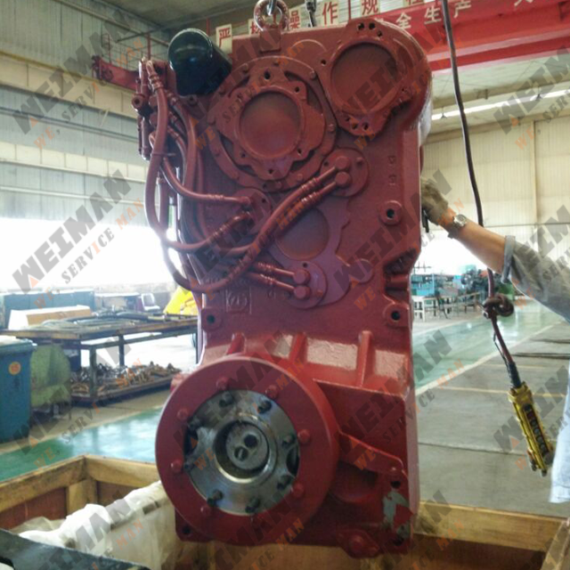
The ZF power gearshift transmission is composed of the hydraulic torque converter and rear-mounted countershaft transmission with multi-sheet friction clutch. The SDLG 938L、948L wheel loader adopts the 4WG158 gearbox assembly ,the SDLG 958L、959、968 wheel loader adopts the 4WG200 gearbox assembly which can realize speed switching between 4 forward gears and 3 reverse gears. The SDLG G9190 grader adopts the 6WG200 gearbox assembly which can realize speed switching between 6 forward gears and 3 reverse gears
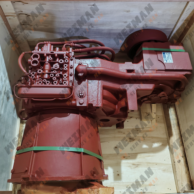
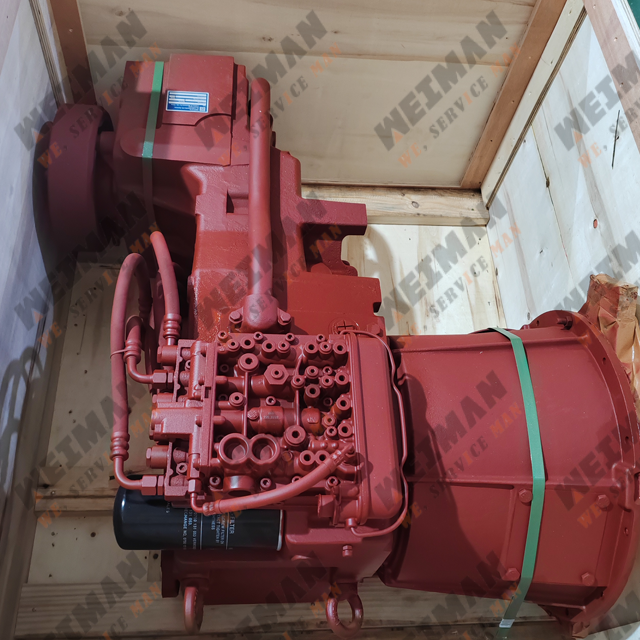
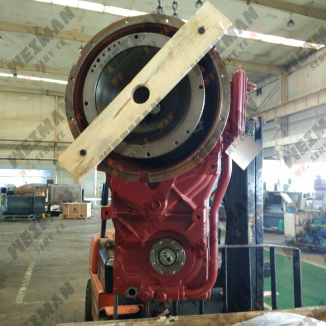
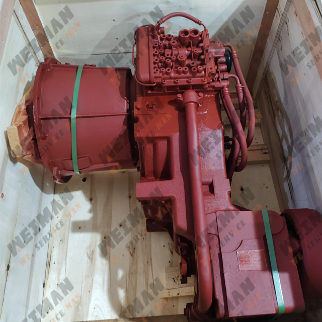
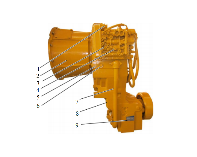 Figure 2-1 | 1. Connecting socket 2. Torque converter shell 3. Transmission control valve 4. Transmission pressure measuring port 5. Torque converter oil temperature measuring port 6. Transmission oil outlet 7. Oil suction pipe 8. Transmission housing 9. Nameplate |
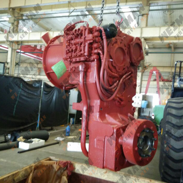
10. Lifting ring screw 11. Oil filter 12. Auxiliary PTO 13. Main PTO 14. KV 15. KR 16. K2 17. K1 18. K3 19. K4 20. Rotation speed sensor 21. Parking brake | 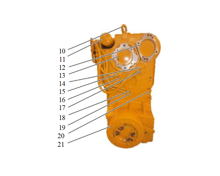 Figure 2-2 |
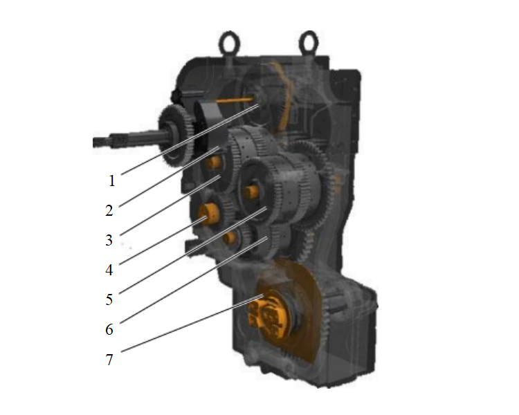 Figure 2-3 | 1. Auxiliary PTO 2. Variable speed pump 3. KVK1 clutch assembly 4. Intermediate shaft component 5. KRK2 clutch assembly 6. K3K4 clutch assembly 7. Output shaft assembly |
1. M4 2. M3 3. M5 4. M2 5. M1 | 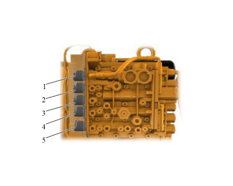 Figure 2-4 |
Basic Parameters of the Transmission-torque Converter Assembly
| Item/Type | 4WG158 | 4WG200 | 6WG200 |
| Transmission gear | Four forward gears and three reverse gears | Six forward gears and three reverse gears | |
Torque converter inlet oil pressure (bar) | 8.5 | ||
Torque converter outlet oil pressure (bar) | 5 | ||
Transmission working pressure (bar) | 16&18 | ||
| Gearbox oil draining capacity(L) | 13 | ||
Mechanical Principles of the Gears ofthe Transmission (4WG158/200)
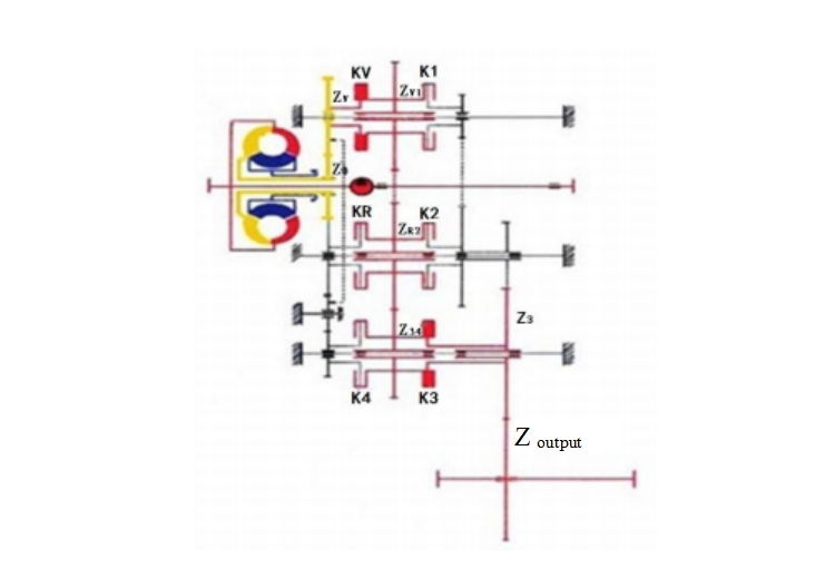
1. First forward gear
Z0→ZV→ZV1→Z1→Z2→Z3→Z output
The solenoid valves M2, M3, M4 act and the transmission pressure oil flows into KVK1 clutch, thus respectively pushing the piston to move; pressing the interior friction lining out of the clutches and forming the transmission subassembly.
The power transmission route: Driving gear Z0→ forward gear input gear ZV→ forward gear clutch KV→ KV1 ring gear assembly ZV1→ first gear clutch K1→ gear Z1 of the first gear→ second gear combination gear Z2→ gear Z3 of the third gear→ output shaft gear Z output→ output shaft, as shown in Figure 2-5
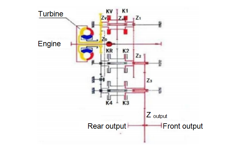
Figure 2-5
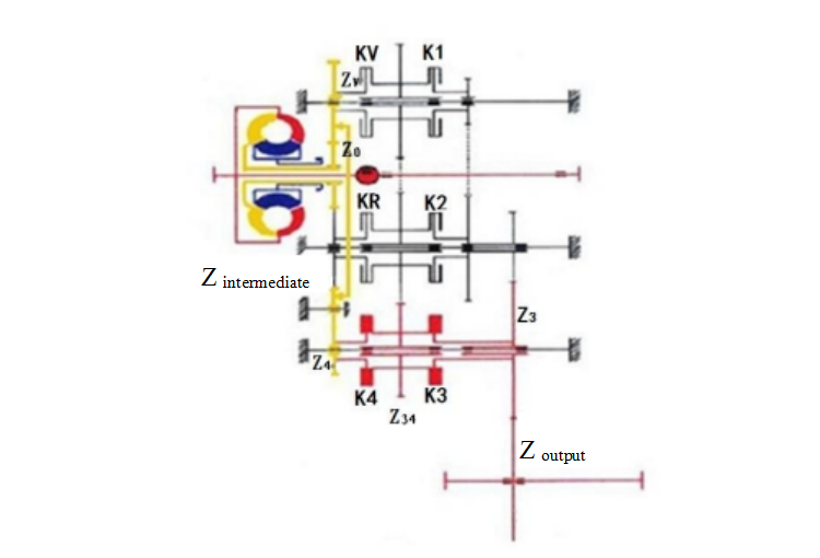
2. Second forward gear
The solenoid valves M3 and M4 act and the transmission pressure oil flows into KVK2 clutch, thus respectively pushing the piston to move; pressing the interior friction lining out of the clutches and forming the transmission subassembly.
The power transmission route: Driving gear Z0→ forward gear input gear ZV→ forward gear clutch KV→ KV1 ring gear assembly ZV1→ KR2 ring gear assembly ZR2→ second gear clutch K2→ second gear combination gear Z2→ gear Z3 of the third gear→ output shaft gear Z output→ output shaft, as shown in Figure 2-6
Z0→ZV→ZV1→ZR2→Z2→Z3→Z output
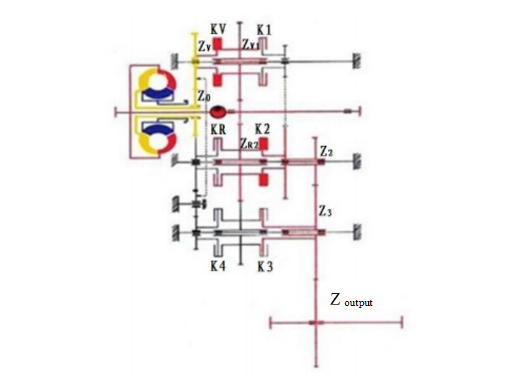
Figure 2-6
3. Third forward gear
The solenoid valve M3 acts and the transmission pressure oil flows into KVK3 clutch, thus respectively pushing the piston to move; pressing the interior friction lining out of the clutches and forming the transmission subassembly.
The power transmission route: Driving gear Z0→ forward gear input gear ZV→ forward gear clutch KV→ KV1 ring gear assembly ZV1→ KV2 ring gear assembly ZR2→ K34 ring gear assembly Z34→ third gear clutch K3→ gear Z3 of the third gear→ output shaft gear Z output→ output shaft, as shown in Figure 2-7
Z0→ZV→ZV1→ZR2→Z34→Z3→Z output
Figure 2-7 |
Figure 2-8 |